
360° AI Surround View Solution
OneKiwi 360° AI Surround View Solution
See Every Angle. Understand Every Risk.
The OneKiwi 360° AI Surround View Solution is an intelligent panoramic vision and safety analytics platform for construction machinery, mining vehicles, agricultural equipment, logistics vehicles and autonomous robotic systems. It combines multiple wide-angle cameras with the OneKiwi RZ/V2H Edge Vision AI platform to generate a real-time Bird’s-Eye View, detect objects, estimate distance and issue proactive safety warnings directly at the edge.
Big blind spots. Bigger consequences.
Construction machinery and industrial vehicles often have large dimensions, asymmetric structures and extensive blind spots. These limitations become particularly dangerous when the vehicle is:
Reversing or turning in a confined area
Tight yards, loading bays and job sites leave little margin for error.
Operating near workers or other equipment
Ground crew and other machines move in and out of the working envelope.
Moving a bucket, lifting arm, crane or attachment
The hazard zone changes shape as the machine works.
Construction sites, warehouses, ports or mining areas
Dense, changing layouts with limited sightlines.
Dusty, high-vibration or rapidly changing lighting
Conditions that degrade an operator's own vision fastest.
Conventional reversing cameras and basic 360-degree systems provide passive visual information. OneKiwi’s solution concept turns panoramic viewing into an edge perception platform that helps operators understand where objects are located, how close they are to the vehicle, and whether collision risk is increasing.
From four camera feeds to one safety decision
The reference configuration uses four wide-angle cameras installed at the front, rear, left and right sides of the vehicle. Camera signals are transported to a multi-channel video front end and processed by a central Vision AI controller based on the OneKiwi RZ/V2H SOM.
Capture
Acquire synchronized or time-aligned video from multiple cameras.
Calibration
Correct lens distortion and camera mounting tolerances.
Projection
Transform each input into a calibrated Bird's-Eye View plane.
Stitching
Blend overlap regions and balance brightness and color.
AI perception
Detect and track people, vehicles and obstacles.
Metric mapping
Map objects to vehicle coordinates for distance and movement.
Risk evaluation
Apply vehicle-specific zones and warning rules.
Response
Operator guidance plus optional audio, GPIO, relay or CAN events.
Architecture note. AHD over coax is the cost-optimized reference path for long vehicle cable runs. Direct MIPI CSI-2, GMSL or another digital camera transport can be evaluated for customer-specific designs. Steps 1–4 form the core viewing pipeline; steps 5–8 are configurable analytics whose performance depends on the project dataset, calibration and validation plan.
Reference System Configuration
| Camera coverage | Four cameras: front, rear, left and right |
| Camera transport | AHD over coax to a multi-channel CSI-2 front end |
| Central compute | OneKiwi RZ/V2H SOM on a custom or reference carrier |
| Primary view | 2D Bird's-Eye View plus selectable camera views |
| Operator output | In-cabin display with visual overlays and warnings |
| Machine outputs | Audio, GPIO/relay and vehicle-network events |
| Data services | Local recording, diagnostics and event logging |
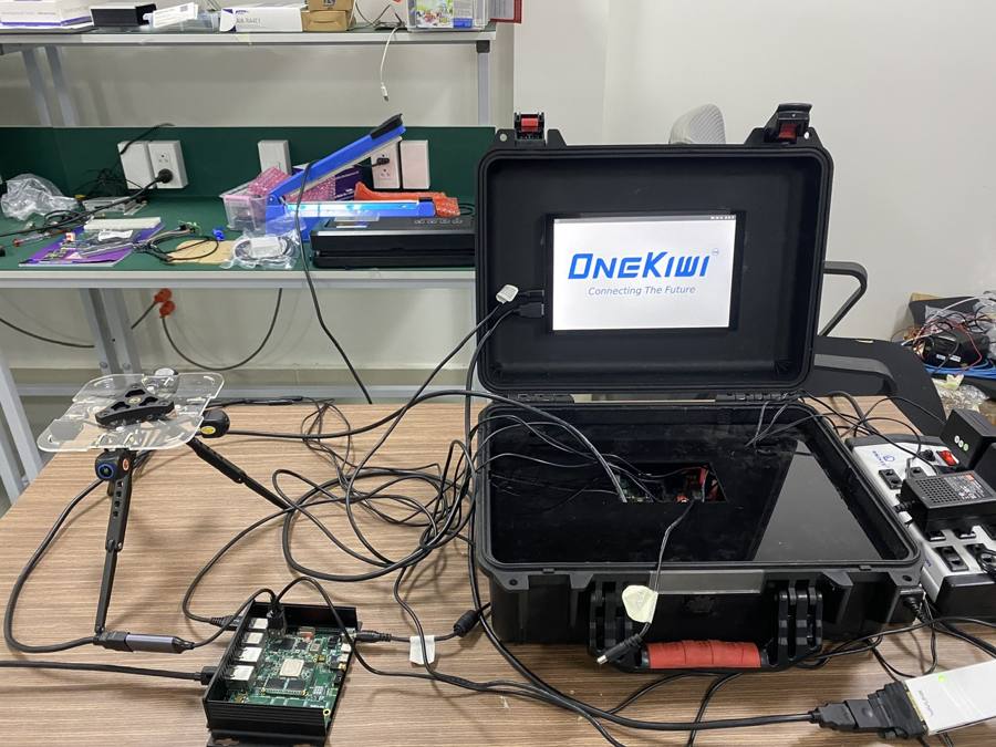
Built and validated on real hardware
The reference configuration uses four wide-angle cameras at the front, rear, left and right, feeding a multi-channel video front end into a central Vision AI controller built around the RZ/V2H SOM. OneKiwi has run the full Surround View pipeline — capture, calibration, projection, stitching — on the hardware shown here.
What the platform does today
Real-Time Bird's-Eye View
Wide-angle lens correction, ground-plane projection, seam blending and brightness/color balancing across all four cameras.
Vehicle-Specific Calibration
Calibrated to camera intrinsics, mounting position, actual vehicle geometry and moving-equipment position — symmetric or not.
AI Object Detection
The DRP-AI3 accelerator runs Vision AI locally, detecting pedestrians, vehicles, obstacles and hazard-zone entries at the edge.
See risk before it becomes contact
Bird's-Eye View Distance Estimation
Distance is calculated to the nearest point on the vehicle boundary, a customer-defined warning zone, or the operating envelope of a bucket, lifting arm or counterweight.
Validation requirement. Publish distance accuracy only after field tests define camera geometry, calibration method, object classes and error statistics.
Relative Speed & Dynamic Hazard Zones
Object positions are tracked across frames to estimate direction, relative speed and approach/departure behavior. Zones can follow the actual vehicle outline and operating state rather than a fixed rectangle — tied to turning path, counterweight swing, bucket movement and machine mode. Safe, caution and danger levels are shown using clear color coding, with thresholds that vary by object type, distance, approach speed and machine state.
One screen, every angle, every warning
The in-cabin display can be configured to show:
- A 360-degree Bird’s-Eye View.
- Front, rear, left or right camera views.
- AI object-detection labels and confidence information.
- Estimated distance, movement direction and optional motion vectors.
- Safe, caution and danger zones.
- Vehicle overlays, projected trajectory and working-envelope graphics.
- Camera health, video-loss, obstruction and system-status indicators.
- Active visual and audible warnings.
Reverse signals, steering angle or vehicle operating modes can automatically select the most relevant camera view.
One heterogeneous chip, six domains
The solution is built around the OneKiwi RZ/V2H SOM — a compact platform combining Linux application processing, Vision AI acceleration, graphics and real-time control resources.
| Application CPU | 4× Arm Cortex-A55, up to 1.8 GHz |
| AI accelerator | DRP-AI3 · up to 8 TOPS dense / 80 TOPS sparse |
| Memory | 8 GB LPDDR4X |
| Camera interfaces | 4× 4-lane MIPI CSI-2 |
The Compute Platform Behind This Solution

SOM Renesas Secure RZ/V2H — AI Accelerator
4× Cortex-A55 · DRP-AI3 · 8GB LPDDR4X — the module powering this solution.
Every table from the solution brief, organized
Entries marked TBD stay out of public performance claims until measured on the selected cameras, carrier board, enclosure and software build.
Rigor before claims
A frozen, delayed or incorrectly calibrated image can create operational risk. The product architecture includes health monitoring for camera presence, frame progression, timing, calibration identity, pipeline status and output validity. If an anomaly is detected, the interface enters a defined degraded or safe state.
- Camera-loss, frozen-frame, timing and obstruction diagnostics.
- Software watchdogs, memory pressure, temperature and critical task health.
- Versioned and protected calibration data, AI models and warning-rule configurations.
- Authenticated software updates with rollback where remote updates are used.
- Documented degraded modes and operator indications for every critical fault.
Functional safety statement. The RZ/V2H heterogeneous architecture can support separation of application, accelerated and real-time tasks, but the complete Surround View product must not be described as functionally safe or safety-certified without a defined safety concept, development process, component evidence and system-level assessment.
Where the platform can grow next
- Automatic or online camera recalibration
- Camera obstruction, video-loss and frozen-frame detection
- 2D and 3D surround-view display modes
- Blind-spot and cross-traffic warnings
- Parking-position, tow-hitch or working-area views
- Video recording and deterministic playback for validation
- Ultrasonic, radar, LiDAR or IMU integration
- Event and analytics reporting to a fleet-management platform
- Customer-specific AI models for specialized environments
- NVR integration and local encrypted video storage
- Vehicle trajectory prediction and dynamic work-envelope overlays
- Multi-level visual and audible warning logic
Where 360° awareness earns its keep
Construction Machinery
Excavators, bulldozers, road rollers, cranes, concrete mixers, loaders and other machines with large blind spots.
Mining Equipment
Mining trucks, wheel loaders, excavators and vehicles operating in dusty, high-equipment-density environments.
Smart Agriculture
Tractors, harvesters, sprayers and autonomous agricultural vehicles.
Logistics, Warehouses & Ports
Forklifts, reach stackers, container-handling vehicles and cargo transportation equipment.
AMRs, AGVs & Robots
Multi-directional perception, obstacle detection, collision warning and navigation support.
Special-Purpose Vehicles
Fire engines, sanitation vehicles, airport vehicles, military vehicles and other custom platforms.
Calibrated to your vehicle, not the other way around
Cost-optimized architecture
AHD and coaxial cabling can reduce camera and wiring cost for large industrial vehicles.
Customizable hardware
OneKiwi can provide the SOM, carrier board, Vision AI Box or full custom OEM hardware design.
Edge AI + real-time, one platform
Application CPUs, DRP image processing, AI acceleration and real-time cores in one architecture.
Calibrated to the actual vehicle
Configured around the dimensions, geometry, moving equipment and hazard zones of each vehicle.
Software-defined expansion
New object classes, warning rules and operating modes without replacing camera hardware.
Support from PoC to production
Vehicle assessment, prototyping, AI development, calibration, BSP integration and manufacturing transition.
From vehicle assessment to production release
Vehicle assessment
Identify dimensions, blind spots, hazardous zones, operating modes and suitable camera locations.
PoC architecture
Select cameras, video transport, carrier board, display, power and vehicle interfaces.
System calibration
Generate intrinsic/extrinsic parameters, Bird's-Eye View transforms, masks, meshes and vehicle geometry.
AI development
Select, train, optimize and validate object-detection or tracking models for the customer environment.
Distance & warning configuration
Define the vehicle boundary, work envelope, hazard zones, thresholds and output logic.
Field validation
Measure view quality, detection performance, distance error, latency, false warnings and usability.
Product optimization
Finalize carrier, enclosure, connectors, power, thermal design, BSP, diagnostics and manufacturing test.
Production release
Freeze the approved specification, calibration process, software baseline, traceability and service documentation.
Documentation & Downloads
Build Your Custom 360° Vision AI System
Developing construction machinery, an industrial vehicle or an autonomous robot that needs 360-degree visibility and intelligent safety warnings? OneKiwi covers cameras, the Vision AI SOM, image-processing software, AI models and production-ready hardware.
Contact OneKiwi